I finally bought a Rigol DS1054Z (hacked to 100 MHz bandwidth) and today I am poking around my handwired tenkeyless keyboard.
Keyboard: The keyboard uses an Arduino Pro Micro ripoff, two 74hc595 shift registers + a couple of bare pins to scan the matrix. The wiring and coding is described in detail in this post.
I connected four probes from the scope to the keyboard’s column 15, 16, 17 and 18. 15-17 are driven by the shift register, column 18 is driven directly by the 32u4 IO:
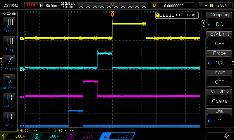
The wave has a period of 882 us meaning that the actual poll rate is not exactly 1 KHz, but close enough. The interesting part is the difference between the two direct IO and the shift register. The duty cycle on the directly driven pin seems to be twice that of the shift register. Let’s investigate!
Looking at the scanning code we have the following loop:
for (uint8_t col = 0; col < MATRIX_COLS; col++) {
    select_col(col);

    _delay_us(3);
    uint8_t rows = read_rows();
    for (uint8_t row = 0; row < MATRIX_ROWS; row++) {
        // Read rows
    }
}

// Debouncing code here.
The debouncing code only runs if a key is pressed so it’s not really relevant for our test.
The select_col method however is. This sets the relevant pins high according to which column we are scanning in the loop. Let’s take a look:
static void select_col(uint8_t col) {
    if (col < 16) {
        writePinLow(COL_SEVENTEEN);
        shift_out(col_values[col]);
    } else {
        shift_out(0);
        writePinHigh(COL_SEVENTEEN);
    }
}
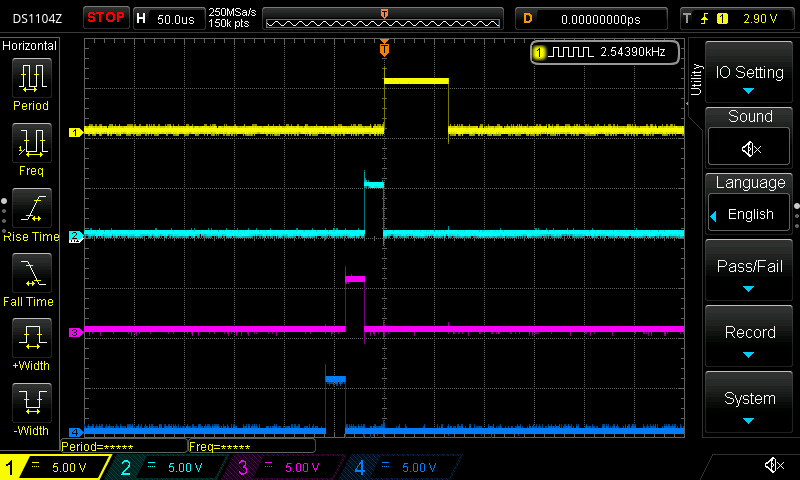
For each column we write stuff out to the shift register. If and only if col == 16 we set the seventeenth pin high. So what’s causing this weird difference and does it mean the scanning code behaves differently when a key on column 17 is pressed? Let’s comment out a bunch of code! We remove all the code that reads the rows and all the debouncing code. The method now looks like this:
for (uint8_t col = 0; col < MATRIX_COLS; col++) {
    select_col(col);

    _delay_us(3);
    /* rest of code commented out */
}

// Debouncing code commented out.
And… the waveform is a little different. The polling frequency increased around 2x to approx 2.5 KHz. We still see a now much longer duty cycle on colum 17:
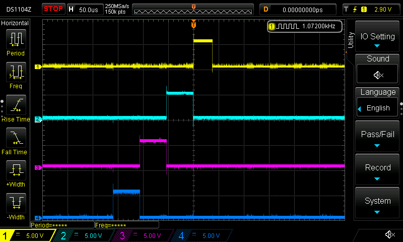
Let’s take another look at the select_col method. When scanning columns 1 to 16 the shift register is invoked and two bytes are shifted out. When we hit the col = 16 we shift out two zero bytes and the shift register pins are set to low. We only set the column 17 pin to low when we select colum 1 again! So the pin is high throughout the rest of matrix_scan method, until the next inovcation of the method and we scan the first column. Let’s fix it byadding a writePinLow(COL_SEVENTEEN); after the column scan loop and in the select_column method we remove the same line:
Conclusion
The longer duty cycle has no impact on the speed or consistency of the matrix scan since the state of the column 17 is irrelevant outside of the for-loop reading the rows. The pin being high could be considered a minor bug, but in practice it’s not a big deal. This was a very fun exercise and a nice introduction to my new scope. It’s facinating to see code you’ve written manifest itself as physical waveforms on a screen. If you look closely at the yellow wave above you can see some 16khz noise. I might want to look into that :)
Thanks for reading if you made it this far. Happy hacking.
/J