Disclamer
This post is about modifying a PSU that runs on mains voltage. Unless you accept the risk of serious injury or death, do not attempt any of the modifications you are about to read about.
The problem at hand
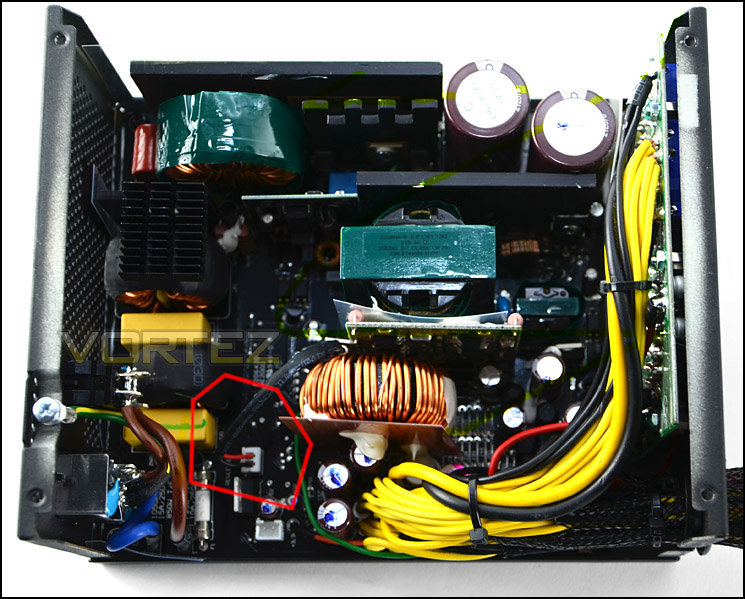
I had an old Corsair HX850 v1 lying around that needed some love, The fan was old and sounded like a broken tractor. The PSU in question is sporting a 140mm voltage controlled 140CFM fan made by Yate Loon Electronics. A thermistor inside the PSU measures the temperature and the built-in fan controller changes the voltage accordingly. This is a 2011-ish model which does not have a “0 RPM” fan mode like newer Corsair models do.
This particular model uses the thermistor as input to a relatively simple circuit consisting of some FETs and a comparator. The result is that hotter temperatures change the resistance of the thermistor, which raises the voltage supplied to the fan. The control circuit simply ignores the fan RPM and relies solely on the feedback from the thermistor. Finding a suitable and silent replacement fan was actually harder than one might think. It needed to run at the very low voltage of 4.2v AND be inaudbile at normal operating loads.
I tried a bunch of fans, and a Fractal branded one I had lying around got close. It did spin at the lowest voltage, but the maximum CFM was merely 60, which is waaay below the 140 the stock fan could deliver. Now this is probably not an issue for light loads, but during the summer running an overclocked Ryzen 1700 and an overclocked Vega 56 my computer can get VERY hot. To be on the safe side I bought a Noctua something something coffee-colored fan. It’s very silent and can deliver almost as much air as the stock fan, the only catch is it doesn’t run below ~6v.
The solution to this is of course pulse width modulation or PWM. How do you PWM a fan? Well you can plug it into the motherboard and control it through there, but then your fan can only react on motherboard/CPU temperature sensors and not on the internal PSU sensor. The standard for fan PWM is from the early 2000s and there are schematics, timings and a whole lot of technical documents to be found on the subject.
My very ingenious solution was to just hook a microcontroller to the thermistor and output a PWM signal to the fan. To PWM control a PC fan by the books you need to be able to run with a 25 KHz PWM frequency. This is not trivial on my <2 USD chinese Arduino ripoffs. It can be done by manipulating the timer registers and doing interrupt handling, which is a cool technique, but I really just wanted to get the hack done and get my computer running without sounding like a hairdryer.
Building the circuit
The microcontroller for this project is the ATMega328 on an Arduino Min clone. This may seem like overkill, but it was cheaper to buy an Arduino clone than a bare ATTiny85 chip. The job of the microcontroller is to read a voltage and convert this voltage into a fitting PWM signal. The Arduino outputs a 500 Hz signal by default, which is WAAAAY below 25 KHz, but lucky for me the not-at-all reasonably priced Noctua fan didn’t seem to give a shit. This could be because 500 divides 25k, or because the not-at-all reasonably priced fan has some high quality circuitry.
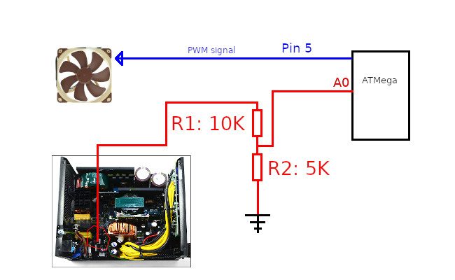
The red wire goes from the thermistor plug in the CPU, a more detailed picture can be seen here. The R1 and R2 create a voltage divider since the voltage after the thermistor was around 6-7v at room temperature. The Arduino in question is 5v tolerant. I used a 10k and a 5k resistor for the divider, yielding a 4v signal for a 12v input, which is close enough for our use case. The code is listed below:
void setup() {
  Serial.begin(9600);

  pinMode(5, OUTPUT);
  pinMode(A0, INPUT);

  // Start fan at 1/2 speed
  analogWrite(5, 128);
}

const uint16_t input_min = 300;
const uint16_t input_max = 400;
const uint16_t output_min = 55;
const uint16_t output_max = 210;

void loop() {
  // Read and map temperature to PWM signal
  uint16_t read = analogRead(A0);
  uint8_t writeThis = map(read, input_min, input_max, output_min, output_max);

  if (read < 100) {
    // Something is wrong, the wire likely broke, put the fan into high speed
    writeThis = output_max;
  } else if (read < input_min) {
    writeThis = output_min;
  } else if (read > input_max) {
    writeThis = output_max;
  }

  // Output PWM signal
  analogWrite(5, writeThis);

  Serial.print("Read: ");
  Serial.print(read);
  Serial.print(" Write: ");
  Serial.println(writeThis);

  // Wait some time before checking again
  delay(50);
}
The code is also on GitHub.
Let’s step through the code. The setup() method initializes the serial port and sets the pins A0 and 5 in INPUT and OUTPUT modes respectively. Then it outputs 128 on pin 5, which is 50% duty cycle, which should set the fan to spin at approximately 50% of the max speed.
In the loop() method we read the value from our analog pin A0 and convert it into a number between 55 and 210. I didn’t make these numbers up, but we will get to that later. There’s a check for if the read value is less than 100. If this is the case the signal from the thermistor is not enough to pull the value up, which is most likely a broken wire or a broken thermistor. In this case we output the max speed which is 210/255. If the read value is less than some minimum, we set the lowest value, and if it is above the maximum we output the maximum fan speed.
Lastly the controller outputs the read and write values to the serial port.
Finding min and max fan speeds
The values for input_min and input_max are 300 and 400, which may seem kind of arbitrary, but they are actually carefully chosen based on some tests I ran with the new fan. To tune in the values you need to find some software that can really push your computer. I went with AIDA64. I set the fan to the max speed of 255 and started the AIDA64 stress test. At the same time I ran FurMark to ensure the GPU had something to do.
After my PC had been running on full load for 10-15 minutes the input readings of the PSU temperature had stabilized. This meant that the heat ouput and fan had hit an equilibrium, which in turn meant I could dial the fan down. I dialed it down and waited 5-10 minutes until it yet again hit an equilibrium. When the fan no longer could keep up with the heat output I had found the sweet spot. I then dialed it up 10-15% and landed at a max of 210.
To find the minimum fan speed I repeated the process, but with the computer idling. I turned the fan speed up from that minimum until it was audible, and landed at a minumum of 55.
Safety
The changes made are merely measuring the voltage of the output of the temperature reading which is used for controlling the fan inside the PSU. This should not have any impact on the shutdown and/or safety mechanisms of the PSU. I carefully tested the overcurrent and overheating protection before and after my modifications.
If you are at all uncomfortable with making these modifications, you should probably just buy a new PSU with a silent fan.
Conclusion
The PSU has been running regularly for about six months and has had no issues whatsoever. The PSU is inaduible at most normal workloads, and even if I peg the CPU a lot, the Noctua fan moves more than enough air to keep the PSU cool. The only time I can actually hear the PSU fan is when the graphics card is running, and when a reference design overclocked Vega 56 is running that’s all you can hear.
Happy modding and stay safe.
/J