The conclusion of my previous post E-bike part 1 was that I needed a spot welder for my battery. The rabbit hole deepens.
Brief intro into spot welding
Welders work by draining a low voltage of say 5-15V with a shitload of current through metal, typically 100A or more. This causes it to heat up and melt. That amount of current is no joke and it can melt steel. A spot welder is just a special type of welding machine that welds tiny cute spots like so:
   +    -

  | |   | | <--- Electrodes
   v     v
==============  <--- Nickel strip
  ---------     <--- 18650 cell, nickel plated steel
 |         |
 |         |
Using a high current DC power source and a couple electrodes you just create a short across two small spots. This causes current to flow. The current flows easily through the electrodes but not so easily through the small contact area between electrode and battery. This melts the nickel to the steel in a ~1mm2 spot. Delivering said current is somewhat tricky because you quickly end up with melted wires or burnt insulation. The wires need to be fairly short and quite thick, something like 16mm2 (6 AWG).
A good spot welder goes for 100s of euros. A cheap one can be had for ~€120 but it’s from China and then the customs fees and sales tax bring it up to around €200. This blows the budget and is boring. Add to that that cheap stuff from China and 100s of amps really shouldn’t mix. I would prefer something sourced in the EU but since I intend to build only a handful of batteries this isn’t really cost effective.
What switches fast and can drain 100A? A beefy MOSFET or a very beefy relay. MOSFETs are fairly cheap and they come in ridiculous amp ratings. AliExpress has a pre-made controller PCB for spotwelding which I ordered as a backup. It looks like it’s just a fairly dumb microcontroller that drives a bunch of MOSFETs. Seems easy enough. So let’s build our own spot welder with parts we have or can source locally!
Ghetto spot welder, the failed attempts
So what is easily accessible and can deliver 100s of juicy lead-acid amps? Why yes just about any car battery made in the last couple of decades. A local scrapyard had one for a smoke and a pancake. The battery in question has a CCA rating of 470A. This means it is RATED to crank 470A under load for 10 seconds, which is, quite literally, an insane amount of current. Time for a back of the napkin calculation! The only load in the circuit is the battery’s internal resistance (5-20 milliohms), the resistance of the wires and less-than-perfect contact between the electrodes and the thing being welded. If you measure the wire resistance it reads in the singular milliohms range. Then there’s the battery’s internal resistance which is around 10 milliohms. If we remember Ohm’s Law and input R = 0.01 we get 12V = 0.01 Ohm * I, which then gives us 12V/0.01 Ohm = 1200 A. If the resistance is 20 milliohms we still get 600A. Even if the numbers are off by an order of magnitude and R = 0.1 we would still have 120A flowing. Most of this energy will be released as heat in the point of most resistance which is the contact between the electrodes and the nickel/steel. This is partly because of the contact surface and partly because nickel and steel are worse conductors than copper. The amount of heat is non-trivial and even at 500A you get 12V * 500A = 6000W. Now if you’ve ever built a desktop PC you know how hard it is to get rid of a couple of hundred watts, 6000 seems very impractical. Luckily we only need to short the wires for somewhere between 1 and 30 milliseconds. At 1 millisecond you still get a theoretical 6 Joules of energy release. That might not sound like much but you can easily weld 0.15mm nickel with 15-20 J, so a measly 3 milliseconds. Now since my last class on Ohm’s law was in high school in 2006, these numbers may be off.
Even if I am off by a factor of 10 this is still very timing sensitive and not something you can control with your puny human reaction time. Enter my friend the cheap Arduino Nano clone, a board powered by an Atmel ATMega 328p. They are very cheap, easily programmable and more importantly they are easy to find a replacement for when you undoubtedly brick them or light them on fire.
First attempt: Starter relay
Yes I know it was stupid. The relay was fairly cheap from china and rated at 200A. I drove it with a ULN2003 darlington array and it worked fairly good with fast pulses of 10-20ms. This was unfortunately not quite enough for a consistent weld. Upping the time to 30ms made the relay jam in the open position, sourcing the current for a second or two until something broke. In all the attempts I managed to pull the circuit apart and avoid any lithium fires.
Why was it jammed open at longer pulses? Sparks or induction. The relay contacts are quite close to each other and a spark may have jumped with the inrush of current. The sparks can actually make a teeny tiny weld on the contacts and jam the relay shut. My other hypothesis is that the staggering amount of current created a magnetic field that overwhelmed the 200A rated spring inside the relay and held it in the open position. Did I mention it was cheap and from China? Yea that 200A rating could just have been a nice paint job, we will never know. All in all this was a good reminder that electrical engineering is called engineering for a reason :)
Second attempt: MOSFET firecrackers
The second attempt was at the time of it’s inception a seemingly fantastic idea: 10 MOSFETs in parallel bolted on to a metal plate. Yes! What could go wrong? Well…
Let’s start by saying that the idea was sound but the execution was sloppy at best. Looking in my parts bin I found 10 FQP30N06L N-channel MOSFETs. Rated at 32A continuous I assumed 10 of them would easily handle the weld. I used a piece of copper-plated aluminum as the base and added a fat, fat wire to handle the transfer from battery negative to source pin on the FET. All of the gates were wired in parallel to the Arduino with a pull-down and a resistor in series. I called him Fetty McFET:
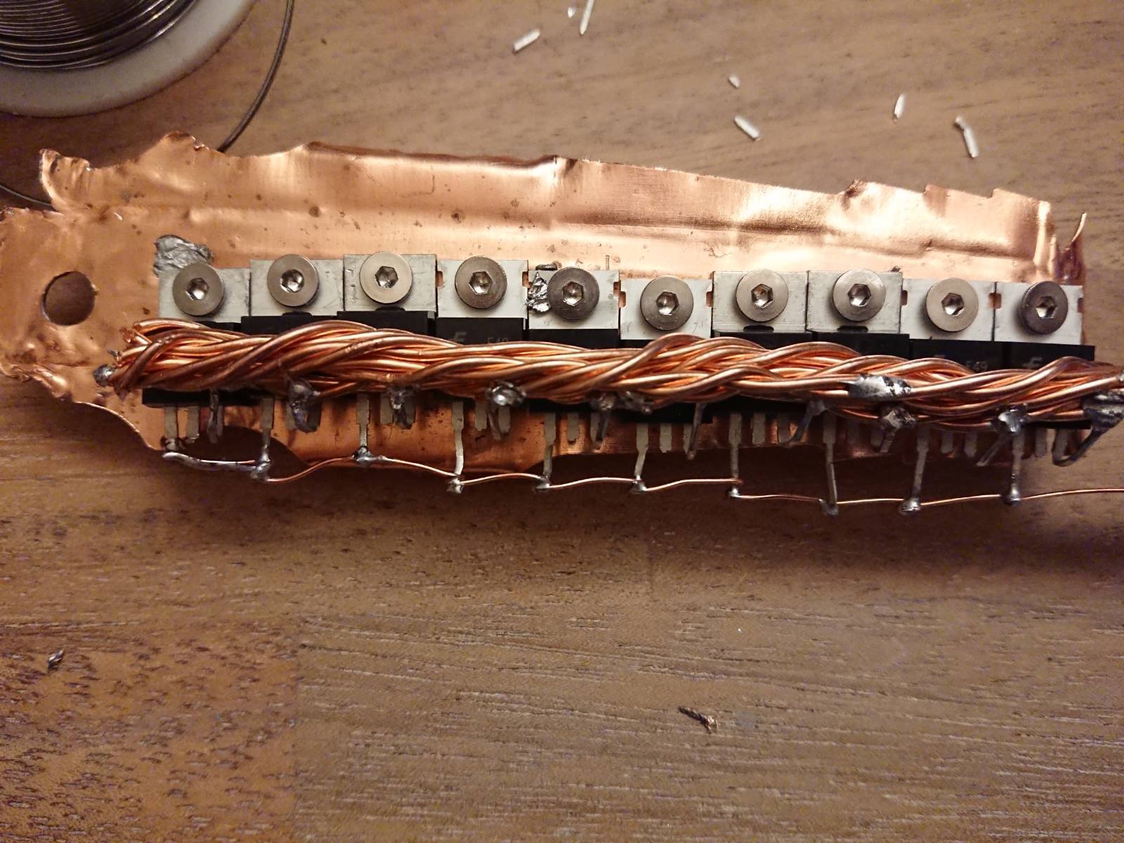
It looks a lot more shoddy than it actually was. Remember that this is a first prototype. The mount and the soldering were good enough but there were some electrical issues. The initial test of the circuit went well. It turned a LED strip on and off at the intervals one would expect. I did not measure the gate timing, but had done the measurement on the darlington array with the relay in place and it checked out. I then set the timing to 10ms and pressed fire on a test nickel strip and voila, I had made a MOSFET firecracker simulator. Within milliseconds Fetty McFET yielded to the force of 100s of amps of current, and all of his FETs broke in an epic cascading failure of electronics popping like cheap firecrackers in the night.
So what happened? The EEVBlog forums helped me understand. MOSFETs can be tricky lille buggers when you have large currents to deal with. The component in question has a threshold voltage of 2.5V, easily achieved by our 5V logic. What I did not consider was two things. First of all gates of transistors have some inherent capacitance. For the FET I used it is around 1000pF, which isn’t much, but when you have 10 of them in parallel you actually get 0.01uF. That’s something you can notice on a square wave. Now I used 5V for the drive which further delayed the FET gate opening. If one of them pops there are less FETs to handle the current and the likelihood of one more popping increases. At 5V from a microcontroller pin, the gate doesn’t have enough kapow to open the FET and drain a shitload current. MOSFET gates can apparently drain amps of current when draining heavy loads. The current rating of the combined circuit was only 320A, which is easily exceeded during a short. Now when one FET pops the current rating drops to 288A and if one more pops the rest follow shortly thereafter. How fast did they fail? I’m not sure, but I know it was faster than 10ms.
The significantly less ghetto (but still kinda ghetto) spot welder
The next spotwelder PCB came from AliExpress from the Czech Republic for just over 13 euros. As seen in the link it’s a small PCB with a couple of quite beefy FETs and a low-end microcontroller. No screens and no real user interface besides a button and a blinking LED. The picture on the listing shows reinforced traces but the PCB I got only had tinned copper. In the package there were some optimistically thin 14 AWG (2.5mm2) wires. The electrodes are 2mm copper with some bent copper holding the rod in place.
There are a total of five reasonably rated MOSFETs. The PCB finish is nothing special, just your ordinary prototype board feel, matte black to ensure no ordinary human can actually see the traces. The finish is probably leaded and there’s no conformal coating. The traces are thick, but seem a little on the thin side for the current I intend to send through them. There are some resistors making up a voltage divider that allow the controller to sense when you short the electrodes and open the MOSFET gates. The short circuit interval is selected with the small button and the LED blinks accordingly. I measured the fastest at 5ms, which is in the right ballpark. The timing selection on the other hand is slow and cumbersome.
I started by tracing out what pin on the controller controls the gates. In my case it was pin 5. Then I lifted the pin to avoid any shenanigans from the controller and soldered on a 2.54mm pin to which I could add the controller from my firecracker simulator.
Next I cut some 1.5mm2 copper wire and soldered it along the traces that carry the current, to which I added significant amount of solder. This should greatly increase the current carrying capability of the PCB. The shitty wires that came in the package got ignored and some beefier 8 AWG cable was cut for the project. The upgraded PCB is not the prettiest but it will be less likely to catch fire when I attempt to actually weld something.
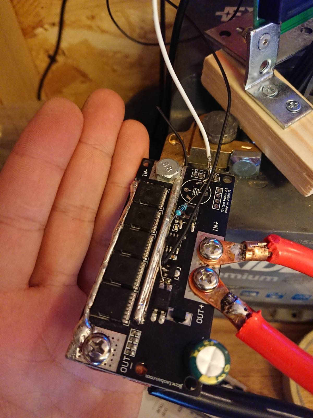
Now the ghetto-ness of this project seems high, but really it doesn’t even qualify for a top 10 of janky shit I’ve managed to run electricity through. Notice the botched resistor? That was added in an attempt to debug why the gates didn’t open when using the firecracker controller. The firecracker reaction had some flyback current and fried the pin on my Arduino so I had to move the control to another pin. The resistor is not really needed but I couldn’t be bothered to fix it.
After some fiddling the MOSFET gates listened and the magical world of custom batteries was now open. Next time we take a stab at welding 50 Panasonic cells with this piece of shit PCB.
Thanks for reading if you’ve made it this far.
/J